Resistivity
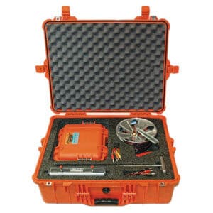
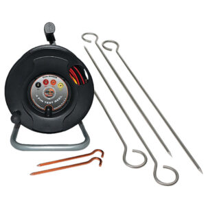
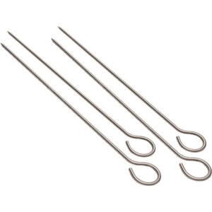
When combined with the appropriate electrodes (pins) and test leads, these resistivity meters can be used to measure earth resistance or the resistance-to earth of a buried electrode, such as a ground rod or an anode, for example. Depending on the application, 4-Electrode, 3-Electrode or 2-Electrode, these resistivity meters can be used to determine the following:
The average earth resistivity to a specific depth (with the application of an appropriate multiplier to convert resistance to resistivity, based on the electrode separation distance) – 4-Electrode Application
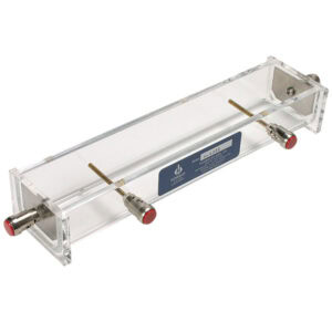
The resistivity of a soil sample, or of a liquid, via an electrolyte (soil/liquid) box (with the application of an appropriate multiplier to convert resistance to resistivity, depending on the box geometry)
4-Electrode Application
• The resistance-to-earth of a buried electrode, such as a ground rod, or an anode, for example
3-Electrode Application
• The resistance between two buried electrodes, such as two ground rods, or two anodes
2-Electrode Application
The current source in these meters, which supplies current between the C1 and C2 terminals (with a load applied), is a 12V(rms) crystal-controlled 97Hz square wave oscillator and the voltmeter inside the unit, which senses the potential difference (voltage drop) appearing across the P1 and P2 terminals, employs a very narrow band-pass filter centered at 97Hz.
What this means is that resistance measurements taken by the meters are unaffected by any stray interference signals (having frequencies other than 97Hz) that may be present in the earth during a measurement. These resistivity meters have a resistance measurement range from 0.01Ohm (0.01Ω) to 1.1 MOhm (1.1MΩ) that is achieved by means of a set of 8 range settings and a system of internal “standard” resistors. External resistances (resistance values under test) are compared against the internal “standards, via a null balancing system, resulting in a determination of the external resistance values.
Showing all 8 results


